After many weeks of careful planning and design, lots of simulations and calculations, and pages upon pages of datasheets, the first revision of the design for the flight computers aboard Martlet 2 are complete.
You can check them out here: m2fc is the main flight computer and m2r is the radio board. Since the radio board is the simpler of the two, we’ll talk about that first.
m2r: The Radio Board
This board is responsible for receiving GPS positions and transmitting them and additional data from the main flight computer over a radio link and a satellite link back to the ground station. At its core is an STM32F303 microcontroller, a powerful ARM-based chip that has several useful peripherals such as a digital-to-analogue converter which we use to drive the radio’s modulator, and three serial ports. It’s also speedy and has plenty of memory, which will come in useful for using error correction codes on the radio data. A handful of LEDs for monitoring, a programming connector, and standard µC support circuitry round out the basics.
For the GPS, we use a uBlox Max-7Q, a very compact and high-performance GPS receiver. A low now amplifier and GPS filter, the ALM-2712, increases sensitivity.
The radio downlink uses a Radiometrix MTX2 unit, generously sponsored by Radiometrix (thank you!). This tiny and high performance radio is the successor to ones we have used on our high altitude balloons, where the 10mW transmit power is enough to receive a balloon from 700km away. It has an FM input that maps to a narrowband output, so we can use it for FSK when received with an SSB receiver, or with any baseband signal when used with an FM receiver (at the cost of some signal to noise ratio). Additionally the MTX2 can be programmed to operate over a wide range of frequencies, so we can resolve any potential clashes or avoid local noise sources.
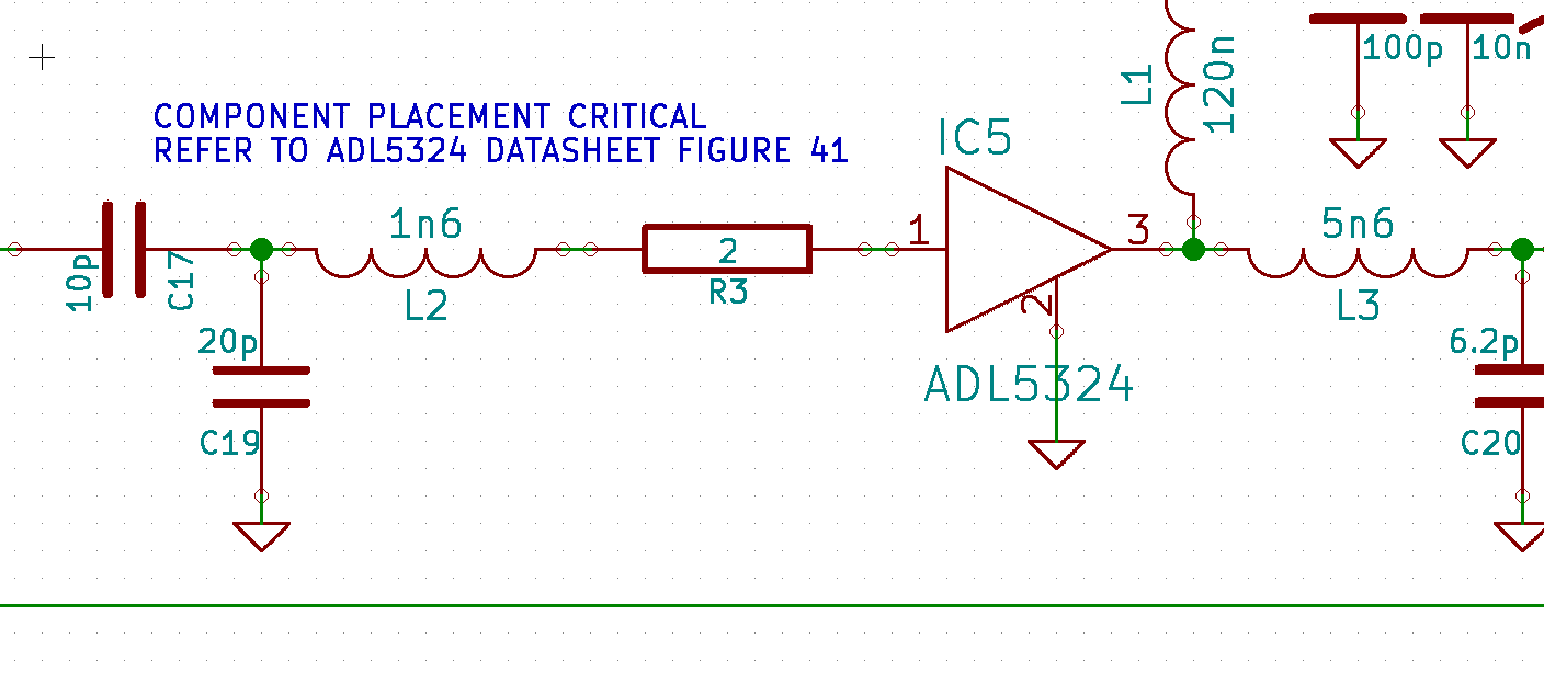
Following the MTX2 is an optional amplifier stage. In the UK this won’t be legal to fly, so we can bypass it for testing, but in the USA it would be OK to operate under an amateur radio licence. The amplifier boosts the output power up to 500mW, which should help it punch through the rocket and reach the ground station. This is the most careful part of the board design, where the best bet is following the ADL5324 datasheet’s recommendation as closely as possible.
To talk to the main flight computer we use the ADuM1201, a more modern version of the optoisolators of the past. This chip provides galvanic isolation via an in-silicon transformer, so that anything upsetting that might come in the cable is prevented from affecting the rest of the board.
For the satellite modem we connect to a RockBLOCK unit, which uses the Iridium network to provide worldwide coverage (so long as the antenna is pointing up!). This is a backup to the MTX2 in case the rocket goes out of radio range or we experience a radio failure. It sends less data and does so slower, but should be useful for getting a final GPS position after landing.
m2fc: Flight Computer
The main PCB has a longer list of responsibilities:
- Measure rocket acceleration, rotation, altitude and bearing
- Fire pyrotechnic devices at appropriate moments in the flight
- Measure strain gauges to determine fin loading
- Measure thermocouples
- Log data to SD card
- Communicate with the radio board to have key telemetry (altitude and flight status) sent back to the ground station
To get all this done we start with an even beefier microcontroller, the STM32F405VGT7. In addition to having 100 pins (compare to 48 for the radio board), we get a bump in clock speed (up to 168MHz) and a lot of peripherals (we’ll be using 3 SPIs, 2 I²Cs, 2 USARTs, the SDIO peripheral, 7 ADC inputs, and a bunch of GPIOs). As before, LEDs, programming interface, a voltage regulator and parts like the clock crystal come as standard.
The SD card here uses the SDIO interface rather than the commonly used SPI interface. The SDIO interface is faster, and on microSD cards can transfer a nibble at each clock, rather than just one bit. Additionally this means we can use the SPI peripherals for other things.
For the inertial sensing, we have a full suite of MEMS sensors. ADXL345 and ADXL375 provide low- and high-G acceleration sensing over SPI, with an output data rate of 3200Hz. The L3G4200D measures the rate of rotation at 800Hz, the HMC5883L measures the magnetic field strength which we can use to estimate a bearing, and MS5611 measures absolute barometric pressure, from which we can derive the current altitude. We’ve hooked each sensor to its own communication peripheral on the STM32 to help avoid bus contention, simplify programming, and ensure maximum data rates. Other than that there’s nothing particularly exotic going on here — the joy of highly integrated sensors.
The serial interface uses a variant on the ADuM1201 on the radio board: the ADuM5201, which in addition to data isolation provides an isolated 5V power output, which we use to power the radio’s ADuM1201. This handy feature means there is complete isolation between the two circuit boards. A second ADuM5201 is provided for futureproofing and connection to a computer for debug and development purposes.
An external red/green LED lets the user know in the field that everything is OK with the set up. The flight computer can check that all the sensors are working, run self tests, verify that the SD card is recording data, communicate with the radio board, ensure satellite and GPS lock, detect the pyrotechnic devices are installed correctly, and ensure all the sensor values are close to nominal before asserting that everything is ready to fly.
The two pyro channels are able to drive 1A into a Metron protractor unit, a small pyrotechnic device which we use for staging and parachute deployment. Continuity detection is provided so the microcontroller can verify that the connections to the devices are OK, and a large capacitor provides the energy to blow the pyro.
The thermocouple design starts veering into actual analogue work. Thermocouples are temperature sensors that operate on the Seebeck effect, producing a very small voltage proportional to the temperature difference between two metal-metal junctions. One junction is at the sensor, measuring the temperature of the fin leading edge, for example. The other junction is at the PCB. Here a speciality thermocouple amplifier, the AD8495, is used to provide both amplification of the very small voltages from the sensor and cold junction compensation. Before the amp is an input RC filter to reject any radio noise picked up on the long leads to the thermocouple. After the amplifier is a two-stage, fourth-order Butterworth antialiasing filter, to ensure that no frequency content above the Nyquist frequency of the ADC is present.
Finally the strain gauges. These sensors are affixed to structural elements of the rocket and change resistance in proportion to the material strain. The change in resistance is detected using a bridge circuit, and the very small voltage amplified up with an AD8226 instrumentation amplifier. Extra care has to be taken that the references are precise and temperature effects are controlled and compensated for, as they are usually of the same magnitude (or larger!) than the voltages due to strain. Here, one half of a Wheatstone bridge is formed of two high-precision and low-temperature-coefficient resistors on the PCB, providing an accurate Vcc/2 reference. The other half of the bridge is on the fin, with one strain gauge and one 120R completion resistor. They should both be at the same temperature, which helps remove that influence. Some factors are not controlled for — the wires leading to the strain gauge will have a resistance, for example, and that will change with temperature. This would lower the voltage across the bridge, and affect the calculations of the strain from the measured voltage. However, some simulations suggest that this impact should be very small as the wires are short and reasonably well behaved. As with the thermocouples, an RF filter is present on the front end, and a fourth-order antialias filter completes the setup.
The next stage is to design the printed circuit boards for both of these schematics. Many other considerations apply here, as component layout and routing can have a big impact on performance. Hopefully no big changes will have to be made to the schematic once work is underway on the PCBs!